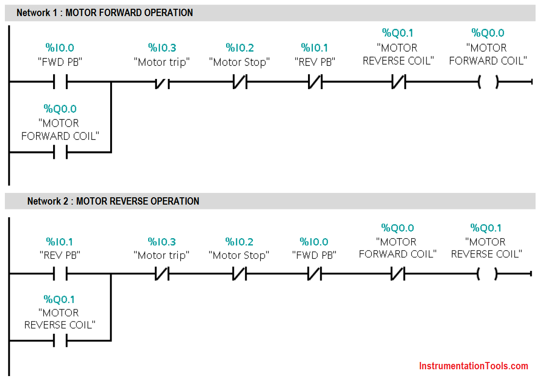
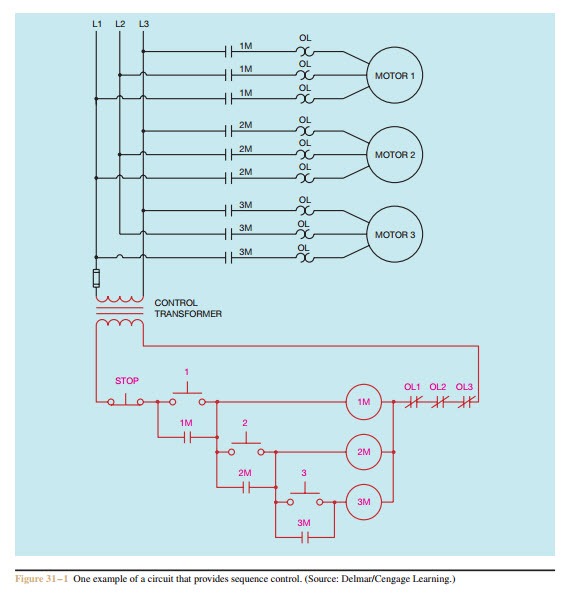
Three phase electrical wiring installation in home iec nec. One motor cannot start until some other motor is in operation.
This is an overview of the basic structure of sfcs.
Sequential control of three motors diagram.
Facebook twitter linkedin tumblr pinterest reddit vkontakte skype messenger messenger whatsapp telegram share via email print. The program is used to carry out the sequential switching on our 3 motors a b and c when the start switch is closed motor a starts 10 seconds later motor b start and after 30 sec motor c start draw the ladder diagram of control. One example of electrical control applied to ma. Figure 6 shows that there is only one transition condition for step 2 and step 3. A simple circuit diagram of contactor with three phase motor. Control motors protection a simple circuit diagram of contactor with three phase motor.
There are total 3 motors to be controlled in a sequence. If either out 2 or out 3 is realized along with the transition condition in 4 step 4 is activated. So that each motor will start sequentially say motor 1 will start then after some delay then motor 2 will start and after some delay motor 3 will start. With this knowledge ladder logic diagrams can be converted to sequential function charts ad vice versa. In industrial processing operation there are cases where machineries should be started one after the another. Three conveyer control by.
The diagram for motors that started sequentially four motors. Enjoy the videos and music you love upload original content and share it all with friends family and the world on youtube. The control diagram of three motor sequential on change to logic program. Sequence control forces motors to start or stop in a pre determined order. Multi speed 3 phase motor 3 speeds 1 direction power control diagrams one line diagram of simple contactor circuit. 19 less than a minute.
Sequence control is used by such machines as hydraulic presses that must have a high pressure pump operating before it can be used or by some air conditioning systems that require that the blower be in operation before the compressor starts. 19 less than a minute. So that whole operation will take 10 seconds to start all motors in a sequence.

3 Phase Motor Control Using Plc Ladder Logic Tutorials Point 5 Pin Flat Trailer Plug Wiring Diagram
Https Encrypted Tbn0 Gstatic Com Images Q Tbn And9gcqkflpb 9dl1n7ljydiadkxnyk1cb4beukrmkayiftp9 F8yp D Usqp Cau 2004 Chevy Venture Radio Wiring Diagram
